Boeing Project - Part I
Northwestern University: Final Project
Technical Skills
- 3D CAD with Onshape
- PCB Design with Eagle
- Soldering
- Wiring Design
- Arduino Mega microcontroller
- Ubuntu 16.04 LTS
- Intel NUC Kit NUC7i7BNH
Introduction
As explained on my Project page, this robot is a programmable mecanum wheel vectoring robot. This means that by commanding the wheels to go at different velocities, it can move forward and backwards and from side to side. Each wheel is rotated by a single 285 RPM motor via a chain/sprocket setup. In turn, each pair of motors are hooked up to a Sabertooth Dual 25A Motor Driver which can supply each motor with up to 25A and allows for Serial communication. The Sabertooths are then hooked up to two pairs of TX and RX pins on the Arduino Mega with a Kangaroo Motion Controller in between them to provide feedback control. To power the whole system, two 12V batteries are hooked up in series. On top of this 'mobile platform' (which also has a metal 'table top' with four legs that goes above the chassis), Matt will place an inverted Delta robot arm that he designed which will be used in future tests to manipulate a rigid object representing a scaled down airplane wing.
Mechanical Structure & Layout
There were two main issues with the original structure and layout of the robot. In the left part of Figure 1, one can see that the Arduino Mega, a Hokuyo laser scanner, and an IMU are placed on the left side of the chassis top. Similarly, on the right side there are some busbars which allow the batteries and Sabertooth Drivers to be easily connected to one another. Unfortunately, the acrylic and wood pieces that the components are bolted to are not screwed onto the chassis and can easily fall off. Additionally, spacing between components is not optimized. Furthermore, in the original design, a laptop had to be placed on top of the table top (where the Delta arm would go) to control the Arduino.
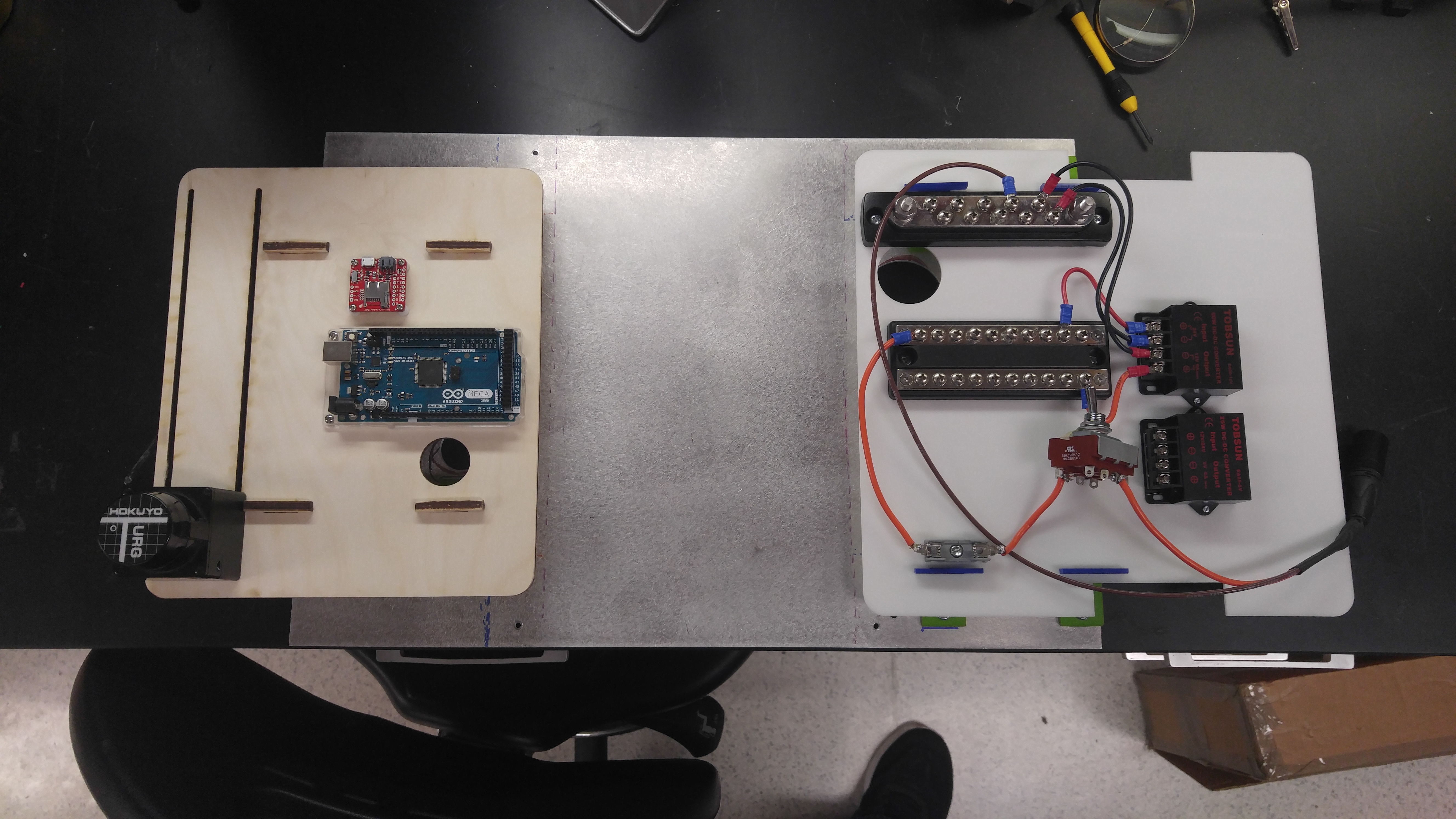
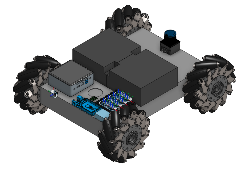
Figure 1: Original layout of components (left) & Suggested layout of components (right)
In the redesign of the layout (right part of Figure 1), the batteries would lie across the middle of the chassis top (although not shown, this is how it lay in the original setup as well), dividing the 'Power & Control' section to the back of the robot and the 'Sensor' section to the front. In the 'Power & Control' section would be the Intel NUC (replaces the laptop), the Arduino Mega, DC/DC converters, and terminal blocks. In the 'Sensor' section would be any neccessary sensors useful for navigation (such as a laser scanner or camera). Besides for keeping all components within the confines of the chassis area and replacing the laptop, this design also focuses the majority of any wiring to the back of the robot which gives a cleaner look.
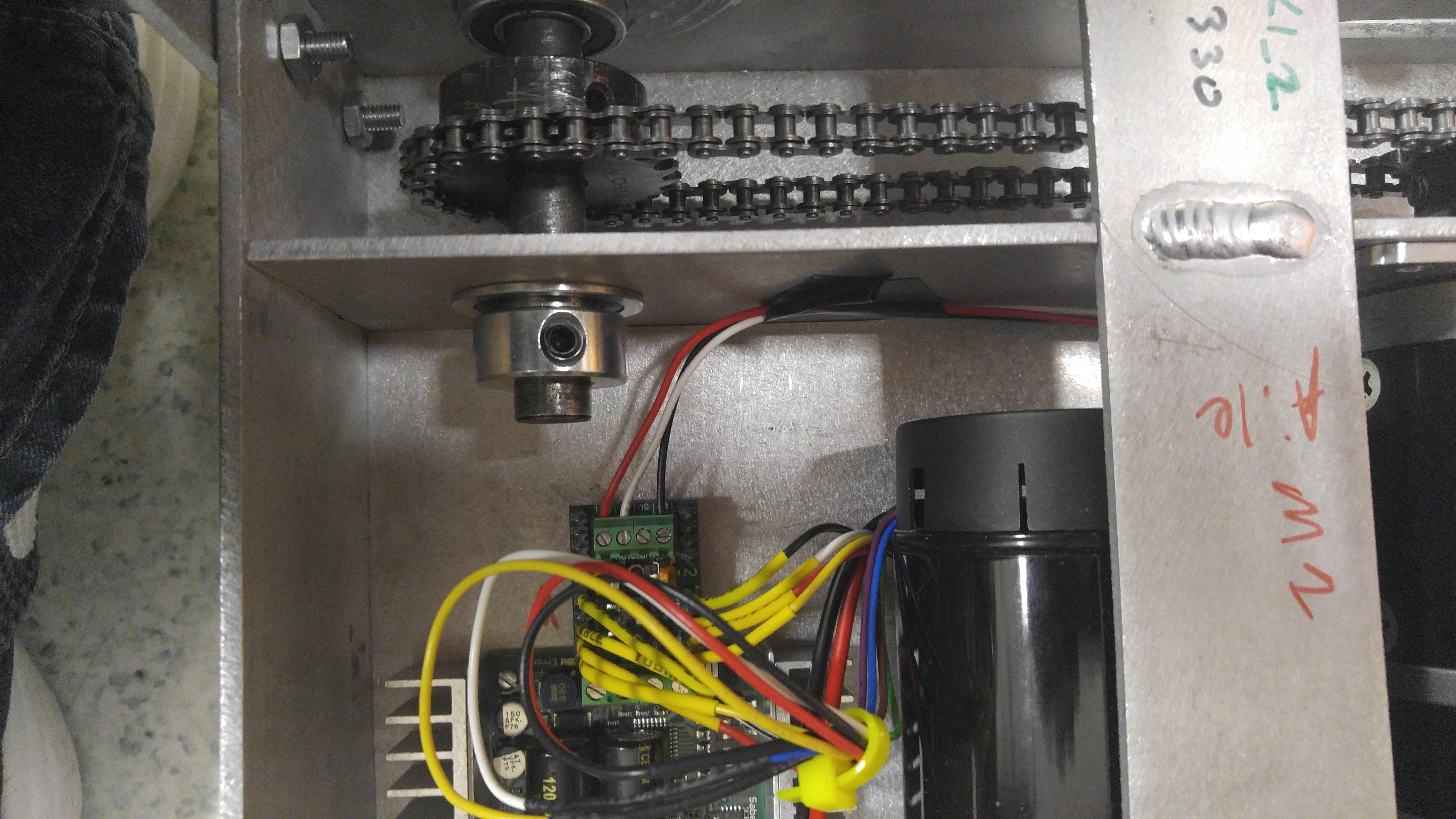
Figure 2: Sprocket & Chain
The second problem was that the kit came with sprockets that could only be held in place on the axle using set screws (as shown in Figure 2). As a result, it was not uncommon that the set screws would loosen over time so that the sprocket would end up free spinning around a stationary axle. Fortunately, after doing some research, my teammate (Aamir Hussain) and I found that SuperDroid had updated their robot kit since last year to include a keyed shaft/sprocket setup which essentially eliminates this issue. Needless to say, we purchased the updated parts.
Hardware
To replace the bulkiness of a laptop, we chose to use an Intel NUC Kit. Besides for having a small 4x4 inch footprint, it also boasts an i7 processor, Wifi & Bluetooth capabilities, 4 USB ports, and the ability to customize RAM (up to 32 GB) and storage. Additionally, it can be powered using a voltage between 12 and 19 volts. In order to isolate the NUC from the motor circuitry, we chose to use a Cincon isolated DC/DC converter (capable of converting 24V down to 15V at 6.7A and 100W output power). Since the NUC is capable of consuming a max of 65W at 3.43A, this converter should be more than sufficient to do the job. Lastly, we purchased some ISO3086DWR IC chips which are capable of isolating signals up to 2500Vrms. These chips, as discussed in the next section, will be used to isolate signals coming to and from the Arduino and the Kangaroo motion controllers.
Electrical Design & Safety Measures
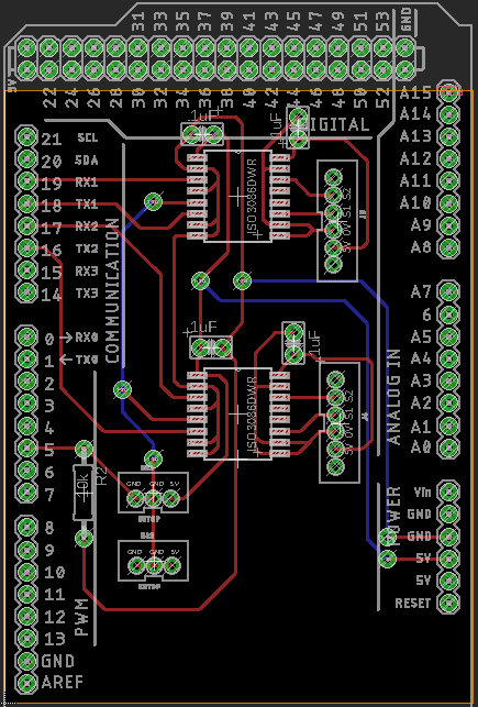
Figure 2: Eagle PCB Design
There were two parts to the electrical design. In the first part, Aamir focused on determining the best way to incorporate an E-Stop into the robot as well as what gauge wire to use in different parts of the circuitry. In the second part, I focused on designing an Arduino Shield with two main functions: 1) to develop isolation between the Arduino and the Kangaroo motion controllers and 2) to replace loose hanging Arduino wires (originally connecting the TX and RX pins from the Arduino to the Kangaroo motion controllers) with much stronger JST connections. There were some constraints, however. For one, the PCB had to be single-sided (as it was made using a CNC mill), and two, all 'low-side' (i.e. Arduino) traces had to be on one half of the board with all 'high-side' (i.e. Kangaroo) traces on the other half to reduce the chance of possible shorts. Thankfully, the ISO chips are symmetric with the left 8-pins belonging to the 'low-side' and the right 8-pins belonging to the 'high-side'. Finally, all 'bottom' (i.e. blue) traces just became wire connections.
The way the ISO chips work, two of the pins on the left side are connected to a pair of TX and RX pins on the Arduino. On the other side of the chip, two pins are connected to the S1 (RX) and S2 (TX) pins on a Kangaroo motion controller. Then, to allow communication from the Arduino to the Kangaroo, a 'Driver-Enable' pin must be pulled high. Without the 'Driver-Enable' pin pulled high, the Kangaroo would not recieve any commands and due to a built-in safety feature, would stop the motors. This then became the 'break-in' point for the E-Stop. With the E-Stop in a 'normally-closed' position, the 'Driver-Enable' pin would be connected to the Arduino's 5V. However, with the E-Stop pressed, the switch opens, and a 10k ohm resistor pulls the 'Driver-Enable' pin low, disabling the output. This change in voltage can then be read by one of the Arduino's Digital Input pins (pin 5 in this case) and used to signal the Delta robot arm to stop moving and hold its position.
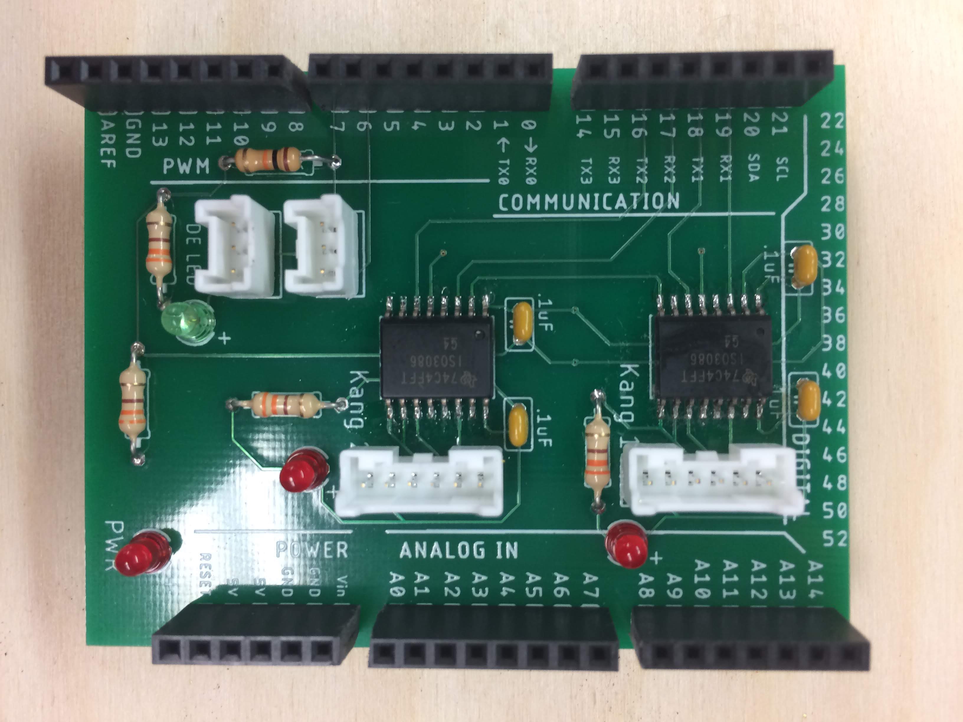
Figure 3: Physical PCB
In Figure 3, one can see the physical PCB layout. Each ISO chip is connected to a pair of Arduino TX and RX pins on the left side and to a pair of six-pin (of which 4 pins are only being used) JST housings on the right. Each of the six-pin JSTs then connect to one of the Kangaroo motion controllers. On the left side of the board, the three-pin JST closest to the 10K ohm resistor connects to the E-Stop while the second three-pin JST can be used to read the status of the E-Stop. Once the complete robot is assembled, this last JST will be connected to the Delta arm so that when the E-Stop is pressed, the arm will hold its position.